If you have any questions please call 973-728-7232.
Disconnect battery before installing:
Unbolt and remove the Rally Sport headlamp door assembly. There are two bolts on the radiator support and two on the fender. The center grille does not need to be removed.
Remove the vacuum actuator bell crank from the headlamp assembly.
Important: The motor and control box marked "D" mounts to the driver’s side, while the motor and control box marked "P" installs on the passenger side.
Three 10-24 sized holes in the motor mount bracket will serve as the motors mounting bolt holes. Center the motor shaft in the bell crank hole and drill three holes corresponding to the holes in the motor mounting plate. Sometimes a plastic tipped hammer is needed to slightly "massage" the back of the headlight housing for motor clearance. This will not interfere with the headlamp operation or headlamp alignment.
Install the supplied 1/8" x 3/4" brass thrust bushing over the motor shaft. The thrust bushing must contact the motor base. In some instances the bell crank hole must enlarged for correct thrust bushing fit.
Secure the motor to the mounting plate using the three supplied 10-24 bolts and Nyloc nuts. Important: To prevent motor arm interference, the 10-24 bolt heads must be on the motor output side of the mounting plate, while the Nyloc nuts should be used on the motor side of the mounting plate.
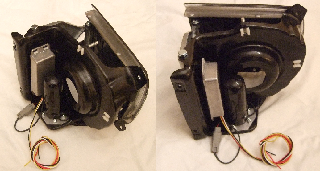
The control box installs directly next to the motor to the side of the headlight capsule (see attached photo). Please install the control box so that the opening for the wires faces downward to prevent water from entering the control box. The control box can be attached using Velcro, 3M Car Accessory tape, silicone glue, epoxy or use zip ties.
Install the supplied 1/8" x 3/4" brass thrust bushing over the motor shaft.
Install the supplied drive washers, plastic friction disks and motor arm onto the output shaft in the following order: steel drive washer - two plastic friction disks - motor arm - two plastic friction disks - steel drive washer (refer to attached diagram).
Slide the supplied cone washer onto the output shaft followed by the supplied washer.
Torque the first ¼" jam nut to about 50 in/lbs. or tight enough to allow the plastic friction disks to slip if there is significant binding in the motor arm. Then jam the second jam nut onto the shaft.
WARNING!: The battery MUST be disconnected before installing control boxes
WARNING!: Wires MUST be installed in the following order or damage may occurBlack wire - Is ground. Connect to any ground source (i.e. the headlamp housing).
Red wire - Is the power supply to the motor and must be connected to a permanent non-switched (always on) power source. Connecting directly to the battery or battery junction is recommended for the passenger side, while the horn relay works well for the driver side. The included 4 amp inline fuse must be used.
Yellow wire - Must be spliced to any low beam wire (tan wire on GM headlight plug).
White wire - Must be spliced to any high beam wire (green wire on GM headlight plug).
Optional:
The high and low beam wires can be soldered directly to the high and low beam headlamp lugs.
Re-connect the battery, install the headlamp assembly and enjoy your hideaway headlights.
Notes:
The motors will perform a closing cycle during initial operation or after power has been disconnected. This is normal. The headlight motor closing cycle is delayed a couple seconds to allow flashing the headlights lights without the RS doors moving.
Specifications
Motor: DC, brushed. All metal with steel planetary reduction
Electronics: SMT/“Through Hole”. Static and surge hardened
Voltage Range: 11 -16 Vdc
Temperature range: 0 - 220 F
Current draw: Motor - 5 A max. Electronics - 0.01 A
Short Protection: Internal fuse, non serviceable.
Wiring: Aviation type, Tefzel/Teflon coated, 16 gauge, 410 F max.
Connectors: Deutsch DTM, weatherproof
Disclaimer: Proper installation should provide years of trouble free use. However, Retro-Electro, LLC assume no liability for any accidents, injury, damage or misfortune resulting from the use of this product.