This FAQ section pertains only to the original 67 RS system and not the electronic kits. If you should have further questions please e-mail us.
Does the '67 RS light switch differ from the standard light switch?
No. Both RS and non-RS used the same headlight switch. Internally the '67 headlight switch is quite simple and can be opened and cleaned without too much trouble.
How to identify the relays.
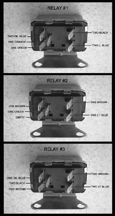
On a 67 RS there are three relays and one circuit breaker under the driver side fender. Relay #1 can be identified by having an orange wire coming from the circuit breaker, while relay #2 is easily identified by having a triple plug with a "missing" terminal. Relay R3 is in line with R2. The relays must the wired as illustrated in the following pictures:
About the relays.
The three RS relays are identical single throw double pole (STDP) relays. Each relay is connected with a double terminal plug and a triple terminal plug. The double plug terminals activate the relay coil (#4 and #5 in the diagram below). The center terminal of the triple plug is the common lead of the switched portion of the relay (#1 of the diagram). The last two terminals of the triple plug are the switched leads (#2 and #3 in the diagram below). For testing purposes, a multi-meter should show a little resistance across the double plug terminal, which would point to a working coil. On the triple plug terminals you would test the common lead across the switched terminals and you should have no resistance on one terminal and infinite resistance on the other. To complete the test, activate the coil and verify that the switched terminals resistance has swapped. Testing the relays does not guarantee proper function. Arcing, pitting, welding and corrosion can cause erratic function long before the relays fail the above test. You could open up the relay case and file the contacts but I have found this to be a short-lived fix, as there must be plating or something on the contacts to resist the welding and pitting. I recommend switching all three relays if you just bought an RS with a non-working light system or if your RS hasn't had an operating headlight system for a few years. Trouble shooting the RS system when you think your relays are OK is a horrible experience.
Where to buy relays.
You can buy the AC Delco's relays from most restoration suppliers or get the Four Seasons PN-35767 from your local parts dealer for less than $10 a piece. The Four Seasons relays work great, has the same mounting bracket, costs half of the AC Delco and differs only in having a silver case, while the AC Delco has a gold case.
About RS circuit breaker.
The RS circuit breaker is rated at 10 Amps. Do not replace it with the identical looking convertible circuit breaker rated at 30 Amps. To check the circuit breaker connect a test light from ground to the orange wire terminal, if the test light does not light the circuit breaker is bad. Note: years of use can weaken the circuit breaker and cause unintended tripping even if there is no short in the system. An identical replacement is hard to find, but similar post-style circuit breakers can be purchased at your local parts store for about $10.
About the RS diode.
The diode is located under the dash about 12 inches down the brown wire from the ignition switch. If it is original, it will be covered with black cloth tape. It is black and roughly the size of a pencil eraser. The diode rarely goes bad. It is there to prevent engine "run-on" and to prevent a complete ground path during door opening. The diode can be replaced by ordering a $40 "under dash RS wire harness" from restoration suppliers, or for about $3 Radio Shack has rectifying diodes, Catalog # 276-1661, that work great as replacements. Also, good diode info can be found at: http://jag-lovers.org/lumps/tech/basics/diode.htm
My doors will not open with the ignition on but open fine with the ignition off.
This is usually caused by a failed #1 relay.
Why do my headlight doors open but not close?
This is often caused by a dirty/damaged headlight switch or failed relays. However, first make sure the ignition switch is on. By design, the doors will open regardless of the ignition switch position but will only close with the ignition switch on. If the headlight switch is OK follow this trouble shooting procedure taken from the Camaro RS Wiring Diagram Manual: First make sure your ignition switch is on. If there is no voltage at green wire terminal of relay #1 (use test light to ground), check voltage at orange wire terminal of relay #1, if voltage is present, replace relay #1, if voltage is not present, check for open circuit breaker or wiring. If there is no voltage at the brown wire terminal of relay #2, then relay #2 and relay #3 (they are wired in parallel) are not actuated. Check for 12 volts across the two-terminal connectors of both relays (use one test lead at each terminal of connector), if voltage is present, replace relay #2, if no voltage, check wiring back to the ignition switch making sure the diode is not open or in backwards. If voltage is pulsating, due to action of circuit breaker, then relay #2 has pulled in but relay #3 has not. Check for 12 volts across the two-terminal connector of relay #3 (one test light lead at each terminal of connector). If voltage is present, replace relay #3, if no voltage, check wiring.
My headlight doors do not open.
First check your circuit breaker. (refer to the "about the circuit breaker" section above). If the circuit breaker is OK follow this trouble shooting procedure from the Camaro RS Wiring Diagram Manual. First make sure the ignition and headlight switch is on. Check the black ground wire from relay #3 to ground at radiator support. This is the motor ground path. Check that relay #1 is energized by unplugging the two-wire connector. The relay should click as the connector contact is broken. If not, use a test lamp between the two terminals of the two-wire connector. The lamp should light if the wiring is OK. If it does, replace relay #1. Check to see that relay #3 is not energized by unplugging the two-wire connector. The relay should not click when connector contact is broken and made. If the relay does click, there is a possible short in the brown wire to the ignition switch. Check with a test light between ground and each terminal of the two-wire connector. The test light should light both times.
My doors "double bounce" upon opening.
Double bounce is usually caused by slop in the door bushings or slop in the drive washers. This will not damage the Retro Electro motors.
How do I test my original or Retro Electro motors?
The two wires from the motor are the only electric leads. You can test your motor on any 12 Volt source by connecting one motor wire to Positive and the other to Negative and then reverse the wires to test the opposite direction.
Why doesn't your replacement motor have the overload bulb fuse?
The little bulb thing on the side of the original motor is a self-resetting overload bulb fuse. In case of door binding from ice, mud, debris, etc., the original motors often did not have sufficient power to slip the Mylar clutch disks and would stall and burn out if not protected by the overload fuse. Our motors are much stronger and do not need an overload fuse because they easily spin the Mylar disks in a binding or jamming situation. We have simulated this on our own Camaro and they spin the Mylar disks with no damage to the Retro Electro motor or other parts. The bulb fuse is not needed. All reproduction motors, including ours, do not use the overload bulb fuse.
This is the original GM RS wire diagram:

How are the limit switches wired?
There are four limit switches on the 67 RS. The limit switch terminals should be wired as follows:
All limit switch ground terminals should face down.
Limit switch located on driver's side of the radiator support: Plug with single purple wire attaches to the top terminal of the switch. Plug with two blue wires attaches to bottom terminal of the switch.
Limit switch located on driver's side headlight capsule: Plug with single grey wire attaches to the top terminal of the switch. Plug with two brown wires attaches to bottom terminal of the switch.
Limit switch located on the passenger's side of the radiator support: Plug with single bright green wire attaches to the top terminal of the switch. Plug with single blue wire attaches to bottom terminal of the switch.
Limit switch located on passenger's side headlight capsule: Plug with single green wire attaches to the top terminal of the switch. Plug with single brown wires attaches to bottom terminal of the switch.